

Whitepaper
Enhancing Barcode Scanner Design
Advantages of an Integrated Solution Based on a 32-bit Microcontroller
Barcode scanners have become such a ubiquitous technology that it is easy to take the complexity of their underlying designs for granted. Barcode scanners require multiple discrete integrated circuits and an array of passive and active circuitry to provide the functionality and reliability that end users have come to expect. Many barcode scanners generally use an optical sensor, such as a charge-coupled device (CCD), which outputs an analog representation of what is “visible” to the sensor to an analog-to-digital converter (ADC) controlled by a microcontroller (MCU). The MCU interprets the ADC’s output as a sequence of thick and thin black and white bars and processes this sequence further to derive a string of characters from the pattern. The character sequence may be encoded in any one of a number of well-defined barcode protocols, such as Code 39. Additional features found in barcode scanners include USB connectivity, regulators, audio output (usually driven by a discrete digital-to-analog converter (DAC) or simple pulse-width modulation (PWM)), and other glue logic for level-shifting between components running from 3 volts, such as the MCU, and components running from 5 volts, such as the CCD.
The design challenge for any developer entering a mature market is to create a disruptive product. A barcode scanner design is a prime example of a well-defined application area in which developers can disrupt the market by providing a more cost-effective, reliable solution that reduces bill-of-materials (BOM) cost and leverages the processing power of advanced 32-bit mixed-signal MCUs.
Charge-Coupled Device (CCD) Overview
The barcode scanner’s CCD optically scans a wide, narrow area and converts optical information into a sequence of analog electronic pulses. Each pulse’s voltage level represents the state of one pixel within the CCD’s scan range. Many commonly used CCDs in handheld barcode scanners produce output at a resolution of a few thousand pixels.
A CCD relies on a controlling MCU to provide a clock source. Clock pulses fed into the CCD’s shift register clock inputs initiate a scan, and the CCD synchronously outputs a voltage proportional to the light to the provided clock. The voltage level describing the pixel state usually contains a direct current (dc) bias, and the voltage swing between optical black and optical white can vary depending on the CCD used and other design factors.
Advantages of an Integrated Solution
In traditional barcode scanner designs, each system feature requires a collection of discrete components. For example, the barcode sensing subsystem requires a CCD surrounded by supporting passive components, a discrete ADC and a controlling MCU. The audio subsystem often requires a discrete DAC, a filtering circuit and a small speaker. The USB subsystem usually requires an external crystal to meet timing requirements imposed by the USB protocol. Developers who find ways to eliminate some of these components can minimize the total build cost of the board, shrink the minimum board size required for layout and reduce the system’s average current draw. In addition, combining more features into fewer components can streamline the development process and speed time-to-market. A highly integrated solution (see Figure 1) also improves system reliability because a design with fewer components reduces potential points of failure in the system.
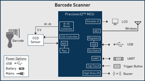
Figure 1. Barcode Scanning System Based on a Highly Integrated 32-bit Microcontroller
For example, Silicon Labs’ Precision32™ 32-bit microcontroller family provides a highly integrated, peripheral-rich embedded control solution that enables developers to eliminate many discrete components in a barcode scanner design while enhancing system reliability and performance.
On-Chip ADC Sampling
When choosing a 32-bit microcontroller with an on-chip ADC, developers must beware of misleading specifications that can narrowly define ADC performance as an operating region in which the device happens to perform well. For instance, some MCU data sheets will not provide a specification that spans the MCU’s entire operating temperature and voltage range. Choosing an MCU whose performance is so narrowly defined leaves a design vulnerable to performance degradation when operating outside of the confines of the ADC’s specification. For instance, an MCU’s ADC might begin to see non-monotonic behavior when operating at high temperatures or when operating at the low end of the operating voltage range.
By selecting an MCU that has been exhaustively characterized and whose performance is specified to cover the broadest possible operating range, developers will ensure that their barcode scanner products function reliably across a wide spectrum of end-customer usage cases. The Precision32 family’s two on-chip 12-bit ADCs provide a maximum throughput of 2 mega samples per second with linearity of less than a single code across voltage and temperature operating ranges. The Precision32 MCU’s high-precision ADCs deliver design performance equivalent to a discrete ADC while saving BOM cost by integrating that functionality into the MCU. Additionally, an on-chip ADC enables the developer to take advantage of the MCU’s ultra-low-power features by placing the MCU in low-power states during autonomous scanning and enabling code to easily toggle power to the ADC between scans.
The ADC subsystem provides additional functionality that makes highly integrated mixed-signal MCUs, such as the Precision32 family, even more compelling for barcode scanning applications. For example, the MCU’s sample sync generator (SSG) can be configured to output a clock source derived from the ADC’s sample clock. The SSG’s clock output can toggle at a rate of 1/16 of the ADC’s clock, enabling the system to output an external clock that is synchronized to the ADC’s start of conversion. This output clock, when routed to the CCD’s shift register input along with another MCU-provided start-of-conversion signal, effectively synchronizes the ADC’s scan rate to the output rate of the CCD’s pixel information. The ADC can be configured to autonomously execute multiple captures and store the resulting data in memory using a direct memory access (DMA) module. This combination of a fast, accurate ADC that can scan the entire range of the CCD’s pixel resolution autonomously means that the developer’s firmware only needs to initiate the first scan and then wait for the final DMA transfer to complete.
Figure 2 shows an example circuit connecting the ADC and port pins of a 32-bit microcontroller to a CCD.
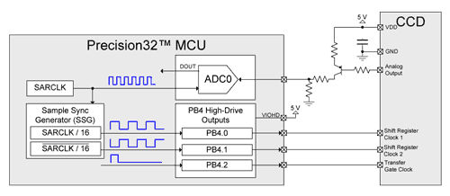
Figure 2. Example Schematic Showing ADC and Port Interface
Pulse-Width Modulations (PWM)
An alternative solution to using an on-chip SSG block for synchronized clocking and sampling involves using one or more PWM channels, which are readily available on most 32-bit MCUs. While a PWM-controlled output offers the essential clocking features necessary for CCD operation, the SSG block provides some significant advantages. When a CCD receives a clock pulse, the device initiates the output of a voltage level to be captured by an ADC. However, the output of the anticipated voltage never appears immediately after the clock edge. Instead, most CCDs begin by outputting a signal representing optical black before the signal settles to the voltage describing the pixel state. The ADC’s start-of-conversion process must be delayed until the CCD’s analog output has settled. Precision32 MCUs, for example, enable hardware configuration to control that timing offset before the conversion begins. When using a PWM, firmware is responsible for delaying the start of conversion, potentially by using a timer module or another PCA channel. Timing jitter introduced by firmware intervention in such a system can result in sample inaccuracies and lead to incorrect or unreliable barcode decoding.
Additionally, many barcode scanning designs require the clocking signal pins to hold state under certain circumstances. In most systems with PWM output, the holding state requires removal of the PWM from the pin followed by configuration of the pin for general-purpose use. During the brief period of time that PWM control is swapped out for general-purpose control, the pin state can be indeterminate, resulting in the output of runt pulses or other unintended signals that can cause the MCU to lose synchronization with the CCD. The Precision32 32-bit microcontroller family’s on-chip SSG block provides direct control over its output pin states, enabling firmware to switch from a hardware block-controlled port pin state to a manually controlled state without the transitional indeterminate pin state.
Managing Multiple Supplies
A system in which devices are powered by both 5 V logic and 3 V logic traditionally requires that level shifting or some other type of glue logic be placed on interfacing signal traces. Additionally, these systems can require separate, discrete voltage regulators to supply 3 V or 5 V where appropriate. Choosing an MCU with an integrated voltage regulator and adjustable port drive levels eliminates the need for this external circuitry. For example, the Precision32 family features an on-chip regulator that can leverage the same 5 V power source used by the CCD to generate a 3 V supply. Additionally, high-drive port pins used by the SSG to drive the CCD’s clock register can be configured to use the 5 V supply as their logic high supply. The high drive port pins may be configured for current-limiting (up to 150 mA source or 300 mA sink) to directly drive an array of LEDs. An on-chip boost converter can also be used to generate a 5 V supply in systems in which a USB-based 5 V supply is not available, such as battery-powered handheld barcode scanners.
USB Communication and Alternatives
Most barcode scanners transmit decoded barcode information to a host system across a USB port. Unfortunately, demanding USB timing requirements force many designs to use an external high-precision crystal as a timebase, which adds to BOM cost, increases board size and can result in reliability issues. The Precision32 family’s USB peripheral eliminates this need by providing an on-chip clock recovery mechanism that generates an internal USB clock compliant with full-speed USB timing specifications without an external crystal. Systems that communicate with a host that is not USB-enabled can communicate information across one of the many other serial interfaces provided by the Precision32 MCU, including UART, USART, SPI, and I²C.
Audio Output
Many barcode scanners provide some form of audible feedback. For instance, the device might beep when the user presses a button to initiate a scan, or the device may audibly indicate that a scan has completed successfully. Traditionally, implementing this feature has required the MCU to connect to a DAC or use a simple PWM to activate a buzzer. The Precision32 32-bit microcontroller family integrates a flexible, high-precision PWM capable of interfacing with Class D amplifier circuits, which are more power-efficient and require a smaller PCB footprint and whose components cost less than many other audio output solutions. The Precision32 family’s high-drive port pins and enhanced PCA capabilities also eliminate the need for much of the external circuitry required by most MCUs.
Summary
Achieving maximum system functionality with the fewest possible components can yield a number of design advantages for barcode scanning products. For example, integrating the sensing, USB, power, and audio output features of a traditional barcode scanner design can eliminate multiple discrete components, therefore reducing BOM cost and board size. Integration also provides additional benefits, such as more precise and controlled power management, simplified code development, and potential improvements in system reliability. Highly integrated 32-bit mixed-signal MCUs, such as the Precision32 family, can handle many of the system-level tasks traditionally distributed among multiple discrete components. Ultimately, this high level of integration enabled by a peripheral-rich MCU solution results in compelling and differentiated barcode scanner designs.