
High Performance, Energy Efficient EFM32™ Peripherals
Silicon Labs' EFM32™ ARM® Cortex®-M 32-bit microcontrollers (MCUs) are packed with peripherals built for low energy operation. Without sacrificing performance, the low power peripherals deliver high throughput and performance, all made possible with the use of innovative control techniques and a Peripheral Reflex System (PRS). Peripherals can react and respond to input from external or internal triggers without any CPU intervention. In combination with the direct memory access (DMA) controller, the PRS-enabled EFM32 systems benefit from an autonomous behavior resulting in reduced latency and energy consumption.
Core and Memory
ARM Cortex-M Processor
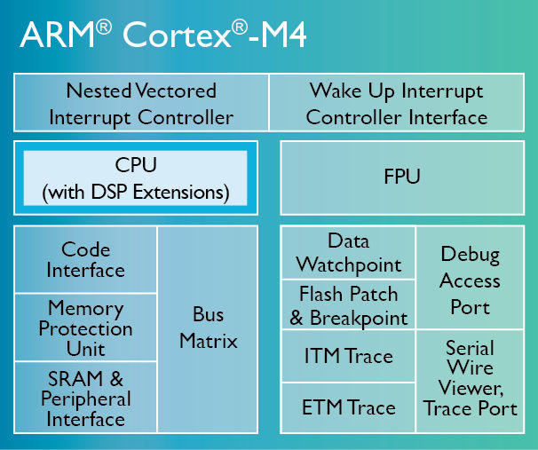
Cortex-M4
The ARM Cortex-M4 processor is designed with a large variety of highly efficient signal processing features applicable to digital signal control markets. The processor features extended single-cycle 32-bit MAC instructions, 8,16-bit SIMD arithmetic and an optional single precision FPU.
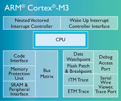
Cortex-M3
The ARM Cortex-M3 processor offers superior efficiency and flexibility and is specifically developed for response and power sensitive applications. The processor features high power efficiency with the Thumb®-2 instruction set, a small core footprint with integrated power mode support and delivers 1.25 DMIPS/MHz.
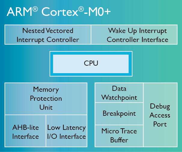
Cortex-M0+
The Cortex-M0+ is ARM's most energy efficient core. The processor is a natural and cost effective successor to 8/16-bit devices, while retaining tool and binary upwards compatibility with the feature-rich Cortex-M3 and Cortex-M4 processors.
Memory and Bus System
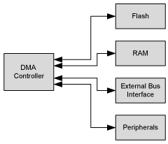
Silicon Labs' EFM32 32-bit microcontroller family has a low latency memory system that features low power flash and RAM with data retention, making operation in low energy modes attractive. The EFM32 contains 4 main memory segments (flash, RAM, External Bus Interface and low energy peripherals) which can be accessed by the ARM Cortex-M CPU or the DMA controller.
Debug Interface
The EFM32 Cortex-M devices use the ARM CoreSight™ on-chip debug and trace interface. Serial Wire Debug technology, specifically the Serial Wire Debug Port for the EFM32, is used as the interface between the on-chip debug module and the development environment on a computer. The EFM32 debug interface makes it easy to reprogram and update the system in field, and allows debugging with minimal I/O pin use.
Debug and programming highlights include:
- 2-wire Serial Wire Debug interface
- Debugging/programming
- 1-wire Serial Wire Viewer output
- Print-style debug information
- PC sampling
- Debug lock for firmware protection
- Pre-programmed Bootloader
- UART in all EFM32s
- UART+USB in parts with USB
- 5-wire Embedded Trace Macrocell (EFM32 Leopard Gecko, Giant Gecko, and Wonder Gecko)
- Instruction and data trace
- Instruction and data trace
Direct Memory Access (DMA) Controller
The DMA controller can move data without CPU intervention, effectively reducing the energy consumption and the workload of the CPU. This peripheral enables the system to stay in low energy modes when moving data, for instance, from the USART to RAM or from the External Bus Interface to the DAC.
- Transfer between flash/RAM and peripherals
- Up to 12 channels
- Multiple, advanced transfer modes (scatter-gather, ping-pong)
- Reduce latency
Clock Management
Clock Management Unit
Clocks and oscillators contribute significantly to the power consumption of MCUs. The clock management unit controls the clocks and oscillators on Silicon Labs' EFM32 MCUs, providing the capability to turn the clock on and off on an individual basis to all peripheral modules in addition to enabling/disabling the available oscillators. With the low power oscillators combined with a flexible clock control scheme, it's possible to minimize the energy consumption in any given application.
The clock management unit features:
- Multiple clock sources (integrated RC and crystal oscillators)
- Current starved oscillators ensures low energy operation
- Low start-up times
- Dynamic system clock division
- Clock prescaler selection for 32 kHz peripheral modules
- Clock gating
Download Application Note:
Clock Management Unit Overview for Series 0
Clock Management Unit Overview for Series 1
Energy Management
Voltage Regulator
All Silicon Labs EFM32 MCUs feature an on-chip voltage regulator, which turns the supplied voltage into correct internal power supply during operation. Independent of the supplied voltage range (1.85–3.8 V), the on-chip regulator generates all the necessary voltages, making it easy to power the EFM32 MCUs.
Voltage Comparator
The voltage comparator provides an easy way to warn if the supply voltage reaches a critical level. While the reset management unit automatically initiates a reset if the voltage level is too low, the voltage comparator compares the supply voltage to an internal bandgap reference. The voltage comparator can also be duty-cycled by software to further reduce the energy consumption and features:
- Dividable VDD in 64 steps selectable as positive comparator input
- Internal 1.25 V bandgap reference
- Low power mode for internal VDD and bandgap references
- Asynchronous interrupt generation on selectable edges
Power-on Reset
When an EFM32 MCU is powered on, the power-on reset monitors the input supply voltage and signals when appropriate operating voltage has been reached, ensuring that the MCU has a correct start-up state. The power-on reset peripheral uses exceptionally low power while monitoring the applied power and sets the cause of reset in the Reset Cause register for use by software.
Brown-out Detector
If the supply voltage falls below the threshold voltage during operation, a "brown-out" has occurred. The brown-out detector will then pull the MCU into reset to prevent unexpected program execution and data corruption. The EFM32 features two brown-out detectors, one for the external unregulated power supply and one for the regulated 1.8 V rail.
Note: Brown-out detector mode is enabled in EM0 – EM3 and is available in EM4 on EFM32 Leopard Gecko, Giant Gecko, and Wonder Gecko MCUs.
Serial Interfaces
UART
Serial communication is frequently used in embedded systems and the UART allows efficient communication with a wide range of external devices. The UART is a very flexible serial I/O module and supports full and half duplex asynchronous UART communication.
The UART peripheral features:
- A wide selection of operating modes, frame formats and programmable baud rates
- A multi-processor mode that allows the UART to remain idle when not addressed
- Triple buffering and DMA support to achieve high data-rates with minimal CPU intervention
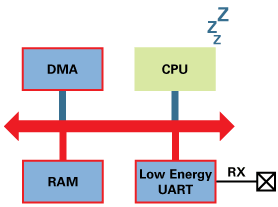
Low Energy UART
The EFM32 low energy UART provides full UART communication using a low frequency 32 kHz clock, and includes the necessary hardware support to make asynchronous serial communication possible with minimal software intervention and energy consumption. The advantage of the low energy UART is its ability to operate in EM2 (deep sleep), while most other modules are turned off for energy conservation.
Download Application Note: Learn More about the Low Energy UART peripheral
USART
Serial communication is frequently used in embedded systems and the USART allows efficient communication with a wide range of external devices. The USART peripheral handles high-speed UART, SPI-bus, SmartCards and IrDA communication and features:
- Asynchronous and synchronous (SPI) communication
- Full duplex and half duplex
- Separate receive/transmit 2-level buffers
- Programmable baud rate
- Various asynchronous and synchronous mode supports
- I²S support (EFM32 Zero Gecko, Tiny Gecko, Leopard Gecko, Giant Gecko, and Wonder Gecko)
- Data can be transmitted LSB or MSB first
- Configurable number of data- and stop bits
- HW collision detection
- Multi-processor mode
- IrDA modulator on USART0
- SmartCard mode (ISO7816)
- Loopback modes
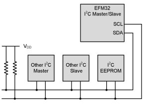
I²C Interface
The I²C module allows simple, robust and cost effective communication between integrated circuits using only one data and one clock line. With the help of DMA, the I²C interface allows I²C communication with minimal CPU intervention. Address recognition is available in all energy modes, allowing the MCU to wait for data on the I²C-bus with sub-µA current consumption.
- Up to two I²C peripherals included
- I²C and SMBus support
- Data rates up to 1 Mbps
- Hardware address recognition in EM3 (stop mode)
I/O Ports
External Bus Interface
The external bus interface is a versatile asynchronous parallel address/data bus that simplifies access to common external parallel interface devices such as SRAM, flash, ADCs and LCDs. The interface is memory mapped into the address bus of the Cortex-M, which enables seamless software access without the need for I/O-level access each time a read or write is performed. The external bus interface may be interfaced by the DMA, thus enabling operation in EM1 (sleep mode).
- The data and address lines can be multiplexed in order to reduce the number of pins required to interface the external devices
- The timing is adjustable and individual per chip select bank to meet specifications of the external devices
- The interface is limited to asynchronous devices (no clock signal is available)
External Interrupts
Silicon Labs' EFM32 MCUs I/O features 16 external interrupts than can be used to signal events and status in the system. The external interrupts can be configured to trigger on falling/raising edges and different levels of priority with the Nested Vectored Interrupt Controller (NVIC). The Cortex-M core processor supports fast, nested interrupt requests and gives the system an exeptional response time and low latency abilities.
Timers and Triggers
Timer/Counter
Most applications have activities that need to be timed accurately with as little CPU intervention and energy consumption as possible. The high frequency timer/counter peripheral keeps track of timing and count events, and generates output waveforms and triggers timed actions in other peripherals.
- Up to 3 16-bit timers
- Up, down, up/down modes
- Quadrature decoder
- 3 compare/capture/PWM
- Dead-time insertion on TIMER0
- Systick Timer
- Integrated in Cortex-M
- OS timer
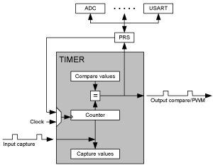
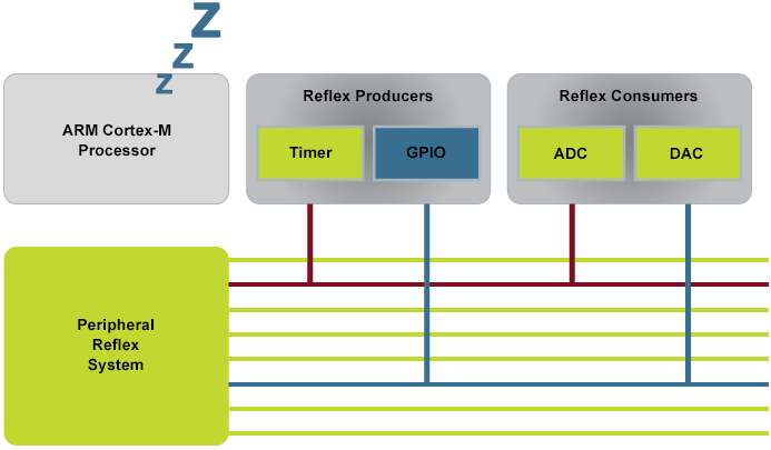
Peripheral Reflex System (PRS)
The peripheral reflex system in Silicon Labs' EFM32 MCUs makes it possible to directly connect one peripheral to another peripheral without involving the CPU. With this system, a peripheral can produce signals which other peripherals can consume and instantly react to while the CPU remains asleep.
Low Energy Timer
The low energy timer can be used for timing and output generation when most of the device is powered down, allowing simple tasks to be performed while the power consumption of the system is kept at an absolute minimum. The low energy timer is also connected to the real time counter (RTC), and can be configured to start counting on compare matches from the RTC. With buffered repeat and top value registers, the low energy timer can provide glitch-free waveforms at frequencies up to 16 kHz.
- 16-bit counter, 8-bit repeat
- Clocked from LFXO/LFRCO
- Waveform generation
- Duty cycle control of external components/sensors

I/O Ports
Pulse Counter
The pulse counter generates an interrupt after a specific number of pulses or rotations are detected, eliminating the need for timing or I/O interrupts and CPU processing. The peripheral:
- incorporates up to 3 8/16-bit pulse counters,
- counts incoming rising or falling edges, and
- includes a change in direction interrupt (asynchronous quadrature decoder).
Real Time Counter (RTC)
Many applications have long time intervals in which almost no activity is required and, in order to save energy, these intervals should be spent in an appropriate sleep mode. The RTC peripheral ensures timekeeping in low energy modes. Combined with the low power 32 kHz oscillator, the RTC can run in EM2 (deep sleep) with current consumption less than 0.6 µA. In EM2 the core and high-speed peripherals are shut down, whereas low-energy peripherals such as the LCD controller, low energy UART and RTC may be enabled.
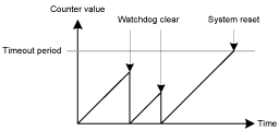
Watchdog Timer
The Watchdog timer increases application reliability by resetting the system to a safe, known state if a software failure or external event renders the MCU unresponsive. An enabled Watchdog timer implements a configurable timeout period, and if the CPU fails to re-start the Watchdog timer before it times out, a full system reset will be triggered.
The Watchdog consumes insignificant power, and allows the device to remain safely in low energy modes for up to 32 seconds at a time.
- Timed reset in case of system malfunction
- Timout from 9 to 256k clock cycles
- Clocked from ULFRCO/LFXO/LFRCO
- Lock to avoid unintentional changes to enable or disable the selected oscillator
Analog Interfaces
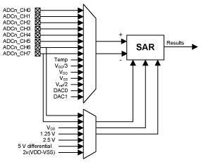
Analog to Digital Converter (ADC)
The analog to digital converter (ADC) is used to convert analog signals into a digital representation:
- 8 external input channels
- 12-bit @ 1Msps at only 350 µA
- Down to 0.5 µA with 1000 6-bit samples/sec
The integrated input mix can select inputs from 8 external pins and 6 internal signals. When using PRS and DMA, the ADC can operate without CPU intervention, minimizing the number of powered up resources. The ADC can further be duty-cycled to reduce energy consumption.
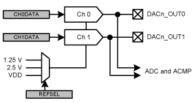
Digital Analog Converter (DAC)
The digital analog converter (DAC) can convert digital values to analog signals using only a limited amount of energy. Using DMA and a timer, the DAC can be used to generate waveforms without any CPU intervention.
- 12-bit @ 500 ksps at only 200 µA
- 2 independent channels
- Continuous, sample-hold and sample-off conversion modes
- Sine generation mode
LCD Controller
EFM32 MCUs include a self-contained, ultra-low power LCD driver with internal bias voltage circuit and boost converter to minimize external components. Consuming less than 2 µA in EM2 (deep sleep), the LCD driver is capable of driving a segmented LCD display with up to 8x36 segments.
The low power LCD driver enables applications to utilize an LCD display even in energy critical systems.
- A voltage boost function enables it to provide the LCD display with higher voltage than the supply voltage for the device
- An animation feature can run custom animations on the LCD display without any CPU intervention
- The LCD driver can remain active in EM2 and provides a Frame Counter interrupt that can wake-up the device on a regular basis for updating data

Analog Comparator
Applications typically need to know the exact value of an analog signal only if it has passed a certain threshold. The analog comparator is used to compare the voltage of two analog inputs, with a digital output indicating which input voltage is higher. Inputs can either be one of the selectable internal references or from external pins and the comparator output can be sent directly to GPIO or PRS.
- Up to 2 analog inputs (one positive and one negative)
- 8 input pins per comparator
- Configurable speed/current4.5 µs / 0.1 µA0.2 µs / 2 µA
- Capacitive sense mode
Security
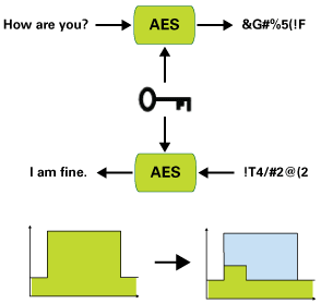
AES Encryption Accelerator
Silicon Labs' EFM32 MCUs include a hardware AES accelerator that can be used with 128-bit block sizes and 128- or 256-bit keys with little or no CPU intervention, significantly reducing encryption/decryption time. The AES module is an AHB slave which enables efficient access to the data and key registers.
- Encryption/decryption
- 128/256-bit keys @ 54/75 cycles
- 20–80 times faster than software
- On-the-fly key generation
- No memory required
- Key buffering in 128-bit mode
- No reload of key
- DMA support for autonomous cipher modes