

Motor Control Applications
Silicon Labs' MCUs and power products offer outstanding mixed-signal capabilities, making them ideal for motor control applications.
Reference designs, application notes, and software examples are available for all of the popular motor types. These examples demonstrate the advantages of high-performance analog peripherals in motor control applications.
Stepper Motor Applications
AN155 provides a complete reference design for unipolar stepper motors using the C8051F300 MCU. The MCU can directly drive 3 V logic-level power MOSFETs. The unipolar stepper motor system provides accurate positioning with the lowest parts count and bill of materials cost.
The reference design board includes a C8051F300 MCU, four power MOSFETs to drive the stepper motor, a diode clamping circuit, a voltage regulator and a RS232 interface. The software demonstrates a linear-velocity profiler with adjustable acceleration.
The software provided in AN155 can also be used to drive bipolar stepper motors with minor modifications. Bipolar motors are driven by a dual H-bridge and utilize the entire motor winding. The lower transistors can be driven directly from the MCU. The upper transistors require a high-side drive circuit. Four inexpensive NPN transistors in the common-base configuration can be used for bipolar stepper motors up to about 24 volts, (depending on the availability of 3 V Logic-Level Power MOSFETs). Note that the polarity must be inverted for the high-side port pins. The bipolar stepper motor has a higher parts count and Bill of Materials cost.
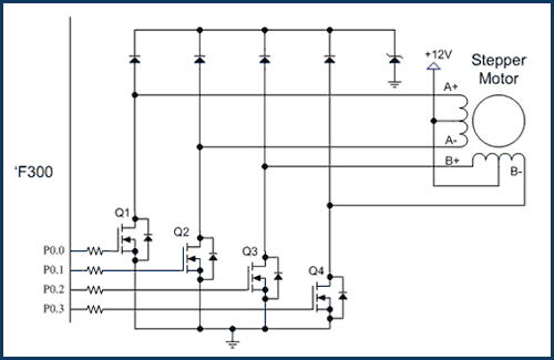
Unipolar Stepper Motor Drive
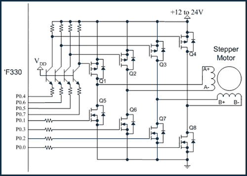
Bipolar Stepper Motor Drive
Brushless DC Motor Applications
Brushless DC motors are normally driven using a three-phase bridge. In this circuit example, hall-effect sensors are used for position feedback. A commutation pattern is used to select which of the six transistors are used.Example 4 of AN191 - Motor Control Software Examples provides a simple example of brushless DC motor control using the C8051F330 MCU. One PCA module is used in the 8-bit PWM mode. The single PWM signal is multiplexed among the bottom three transistors using the Priority Crossbar. The ADC is used to measure the voltage on the potentiometer.
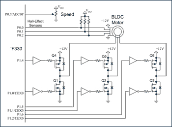
Brushless DC Motor with Hall Sensors
DC Motor Applications
The simplest DC motor drive circuit consists of a single N-channel power MOSFET and a Schottky diode. This circuit provides variable speed control of a DC motor with rotation in a single direction.
Example 1 of AN191 - Motor Control Software Examples provides simple example code for a DC motor using the C8051F300 MCU. The software example uses the ADC and one PCA module configured for 8-bit PWM mode. The hardware based PWM does not require any CPU overhead and leaves 25 MIPS available for user code.
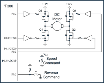
A full-bridge circuit can be used to drive a DC motor when reversing is required. Four power MOSFETs are used to provide variable speed and reversing for DC motors. In this example circuit, the low-side N-channel transistors are used for PWM speed control and the upper transistors are used to chose the motor direction.
Example 2 of AN191 - Motor Control Software Examples provides example code for DC motor with reversing using this circuit configuration.
Abrupt reversal of a DC motor can potentially damage the power MOSFETs. Additional circuitry can be used to sense the back-EMF of the motor and provide safe reversing once the motor comes to a stop.
Example 3 of AN191 - Motor Control Software Examples provides example code for DC motor with soft reversing using this circuit configuration. This example uses the window detector feature of the C8051F300 ADC to measure the back-EMF.
A half-bridge is useful in applications that require unidirectional control with active braking. The half-bridge circuit may also be used to reduce the power losses for larger DC motors. The power losses in the upper power MOSFET may be much lower than using a Schottky diode. Half-bridge DC motor drives require Center-Aligned PWM with dead-time.
Example 7 of AN191 - Motor Control Software Examples provides software example code for Center Aligned PWM with dead-time. This software based PWM code uses three PCA modules and a single Interrupt Service Routine. The Interrupt Service Routine uses only 1.4 MIPS leaving 23.6 MIPS for user code.
A Full-bridge is used in Servo applications that require full four-quadrant control with positive & negative torque and rotation in either direction. with active braking. Four quadrant DC motor drives require four channels of Center-Aligned PWM with dead-time.
Example 7 of AN191 - Motor Control Software Examples can easily be extended to four center-aligned PWM channels. This revised PWM code will use five PCA modules and a single Interrupt Service Routine. The Interrupt Service routine will use only 2.8 MIPS leaving 22.2 MIPS for user code.
The Center-Aligned PWM code can be combined with the quadrature decode code and a simple PID controller to form a complete Servo control system.
DC Motor with Reversing
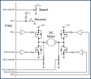
DC Motor with Soft Reversing
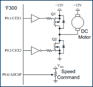
Half-Bridge DC Motor Drive
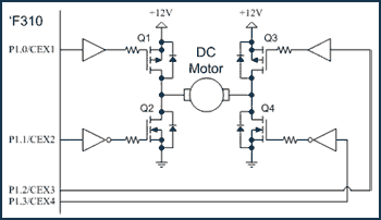
Four-Quadrant DC Motor Drive
AC Motor Applications
AC induction motors require three PWM signals with sine wave modulation. This example circuit uses a three-phase transistor bridge to drive an AC induction motor. Three PCA modules used in 8-bit PWM mode to drive the three-half bridges. This configuration requires the use of a gate drive with built-in dead time. Pull-down resistors may be required to ensure that the lower transistors are turned on at reset.
Example 5 of AN191 - Motor Control Software Examples provides a simple example of AC induction motor control using constant V/Hz control. The three hardware based 8-bit PWMs do not require any overhead. A single timer based interrupt service routine is used to calculate and update the sine waves. The ISR uses less than 1 MIP leaving more than 24 MIPS available for user code.
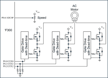
AC Induction Motor